I work closely with customers and partners who want to build a digital twin as a foundation for multiple decision-support use cases. One friction point keeps returning, and it has no easy answer: creating a usable 3D representation of the facility.
Teams in the programs I encounter rarely begin with a clean, current model. CAD may be divided among vendors and engineering systems. Some files describe the original design rather than the factory that exists today. Years of equipment moves, replacement parts and undocumented changes sit between the two. Older areas may have drawings but no usable 3D data.
This creates a large amount of work before the operational part of the twin begins. Files have to be found, converted, simplified, aligned and checked against the physical site. The team can spend more effort preparing the 3D foundation than connecting the first live data source.
In one customer program, creating the 3D foundation for the first production line was itself a substantial project. For the kinds of programs I encounter, that work can range from roughly $50,000 to $250,000, depending on the source data already available, the size and complexity of the area, and how much reconciliation and authoring is required. The larger problem appeared when the team considered additional lines. Finding source files, reconciling them with the current floor and authoring the scene had to be repeated. Scaling the twin did not make that work proportionally cheaper.
The expertise is another constraint. CAD conversion, 3D cleanup, scene alignment and validation usually sit outside the end user’s operations team. An ISV focused on the operational outcome may not keep those skills in-house either. Both then depend on a specialist team before the first KPI, alarm or workflow can be delivered.
That experience reminded me why fidelity has to follow the first use case. CAD can support operational views and provide a path toward simulation-ready geometry later. But if engineering-grade geometry becomes the prerequisite for every line, it can delay uses that need current visual context, stable anchors, asset identity and live state. For those uses, I would rather start with a representation that is good enough for the first decision than wait for one designed to support every future decision.
The purpose changes the model requirement
CAD-to-twin is the familiar route for good reason. A sound CAD or building information model can provide dimensions, assemblies, component names and design intent. Those properties are valuable when the twin supports engineering changes, configuration management, collision checks or maintenance planning.
That does not diminish CAD’s role. It narrows where the authoring effort belongs. Consider an operational view used to show production KPIs, equipment status and alarms over a recognizable factory scene. The operator needs to understand where an event is happening and which asset it belongs to. Visual correctness, stable placement and equipment identity matter. The bolts inside a machine enclosure may not.
Situational awareness covers a related set of operational uses. An operator may need to recognize the surroundings, find a work area or understand production context before going onto the floor. A current visual reconstruction with approved labels can support that orientation. Formal procedure or safety training requires validated content and stronger controls.
These are not exclusive choices. The table treats each technique as a starting point, and a real implementation may combine them.
| Use case | What must be trustworthy | Strong starting point | Practical or combined route |
|---|---|---|---|
| Engineering change or configuration | Dimensions, assemblies, part identity and design intent | Current CAD or BIM | Vendor models plus measured updates for changed areas |
| As-built clearance or layout | Scale, position and known measurement uncertainty | Laser scan or LiDAR | CAD reconciled against scan data, or controlled photogrammetry with survey points |
| Operational KPI and alarm view | Recognizable layout, stable asset anchors, identity and current state | Current CAD/BIM with operational tags | Gaussian splat or photogrammetry mesh with a separate semantic and data layer |
| Situational awareness and operator orientation | Visual context, routes, landmarks and current conditions | Gaussian splat or textured photogrammetry mesh | Textured CAD, panoramic capture or a hybrid scene with guided overlays |
| Visual inspection record | Surface appearance, capture time and source evidence | High-resolution photography or photogrammetry | Gaussian splat for spatial context linked back to the original images |
| Robot manipulation or contact | Metric geometry, collision, joints and physical properties | Physics-ready CAD or mesh | Engineered robot and contact zone with a captured visual background |
The word fidelity can make these choices sound like one scale from rough to exact. A twin has several kinds of fidelity. A scene can look right while its dimensions are wrong, or be dimensionally exact with no equipment identity. Even a geometrically and semantically complete model can be out of date.
NIST’s manufacturing work describes digital twins as fit for a specific purpose. The use case determines the information, model fidelity and synchronization it needs. The task determines where the modeling effort belongs.

One scene can carry several kinds of fidelity
Consider an operational twin centered on a water-treatment plant inside a refinery. The treatment equipment may need accurate CAD, named components, animation and live state. Surrounding pipe racks, access roads and neighboring units provide recognizable refinery context even when they do not need the same engineering accuracy.
Another case is a materials warehouse, where rack assignments, staging zones and storage areas change often. A precise handling-asset model may stay stable while the surroundings become outdated. Here recency matters as much as detail: repeat capture can keep situational context aligned with the current layout.
The same pattern applies to an assembly cell on a shop floor and to the robot training loop. The cell, robot, gripper, task object and contact surface need engineering geometry and physics. The wider shop floor, aisles and nearby machines support situational awareness. A precise asset floating in an empty scene would lose that context.
If someone will measure a clearance, plan robot motion or simulate contact in the surroundings, those areas need scaled geometry and possibly colliders.

OpenUSD can keep the captured visual context, engineered geometry and operational data in separate layers while composing them into one scene. I work through that boundary in detail in A Gaussian Splat Is Not Yet a Digital Twin, which distinguishes reconstruction, visual readiness, operational readiness and simulation readiness. The starting representation should still match the decision, and the layers still need a shared coordinate frame, scale and asset anchors.
Gaussian splatting is one option
Gaussian splatting sits within this larger set of choices. The original 3D Gaussian Splatting work was published in 2023. It starts with photographs and known camera poses, then optimizes a collection of oriented Gaussians so their rendered views reproduce those photographs. Each Gaussian carries position, scale, orientation, opacity and view-dependent color.
I think of the output as a learned appearance model of a specific place. A renderer projects the Gaussians into a new camera view, sorts them by depth and blends them into pixels. It answers a visual question: what should this scene look like from a camera placed here?
The ecosystem has moved quickly since the original publication. The authors maintain a reference implementation. gsplat provides a modular CUDA-accelerated library, and Nerfstudio’s Splatfacto packages Gaussian training into a broader reconstruction workflow. Other implementations add different camera models, ray tracing, browser viewing and editing.
Phone cameras make capture widely available, and training can run on rented GPUs. Those changes lower the cost of trying the technique. They do not turn every capture into a useful twin.
For a bounded visual-context use case and a good capture, that can change the cost by an order of magnitude. A low-thousands path becomes plausible because much of the reconstruction is automated. It is not a like-for-like substitute for the $50,000-to-$250,000 foundation described earlier. The result supplies visual context; engineering geometry, semantics, colliders, scale validation and detailed cleanup remain separate work.
Gaussian splatting is not suitable for every twin, but it is a capable option when visual context is the requirement. It fits remote walkthroughs, visual site records and camera-based robot training, where every pipe and shelf may not need engineering CAD. Camera input also works across sites with incompatible or missing design models.
The boundary remains practical. If I need to approve a 20 millimeter clearance, I want scaled, measured geometry. If a gripper will make contact, I need collision geometry and physical properties. If an operator asks whether pump P-101 is running now, I need equipment identity and current data. Gaussian splatting can still be the right starting visual representation, but it does not carry those other kinds of truth by itself.
It also does not remove the reconstruction work. Image-based pipelines first have to recover camera positions from overlapping views. The COLMAP capture guidance calls for texture, similar illumination, visual overlap and movement between viewpoints for that reason. A useful capture also needs coverage of the views the final experience will expose, a way to establish scale when measurements matter, and a plan for moving objects and reflective surfaces.
One packaged option is NVIDIA Omniverse NuRec, a set of reconstruction and rendering libraries for camera and LiDAR data. NVIDIA announced general availability on March 25, 2026, and the documentation lists version 26.04 from May 2026 as the current release at the time of writing.
For my experiment, I used the mono-camera path built around the open-source 3DGRUT implementation and an OpenUSD export. I started with camera footage of a truck and opened the resulting three-million-Gaussian reconstruction in a viewer.
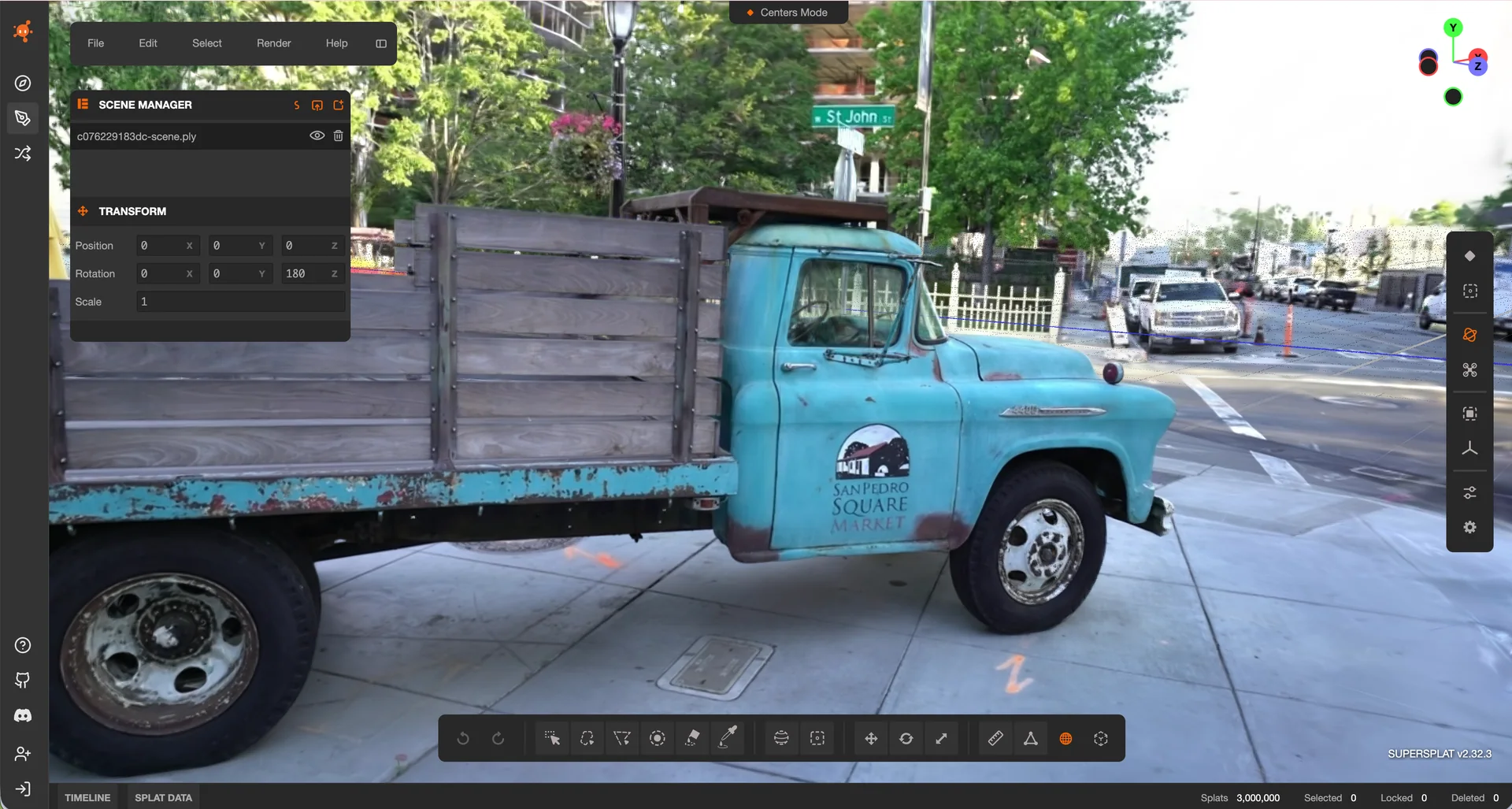
I could orbit the scene, read the lettering on the door and see wood grain on the bed from a viewpoint where no source camera had stood. The result was visually convincing, but the pipeline report contained zero mesh prims, no colliders and no materials. That result captured the exact boundary I wanted to understand.
A mental model for choosing the starting point
I now use five questions before choosing a representation:
- What action will someone take? View an alarm, learn a route, measure a clearance, inspect a surface or train a robot.
- What must be true for that action? Appearance, scale, geometry, physics, equipment identity, current state or some combination of them.
- Which representation carries that truth with the least unnecessary work? CAD/BIM, LiDAR, photogrammetry, Gaussian splatting, a library asset or a composition of several.
- What does that technique require before it can succeed? Current source files, conversion tools, survey control, overlapping images, camera poses, GPU capacity, semantic labels, operational-data access, capture approval and data-handling rules.
- How will the result be checked and kept current? A twin needs acceptance criteria, ownership and an update path that match the decision it supports.
This sequence keeps the technology choice downstream of the use case. CAD remains the strongest source when engineering structure and exact dimensions matter. LiDAR carries measured scale. Photogrammetry produces an explicit textured surface. Gaussian splatting carries visual appearance. Operational twins also need identity, live state and time, regardless of how the scene was created.
The result may be one representation or a composition of several.
CAD-to-twin is a well-established approach and remains the right starting point for many engineering uses. As Gaussian splatting improved and became more accessible, I wanted to test it myself. I chose it for this project to understand the path from camera data to the visual layer of a twin and its limits around geometry, physics and semantics.
The gap between an accessible input and a usable output exposed another problem. Camera solving, training, GPU provisioning, OpenUSD export and reporting still form a specialist pipeline.
That led to a practical question: could someone submit images or video and receive a Gaussian splat, an OpenUSD file and a useful report without operating the GPU pipeline themselves? In Part 2, I cover ReconStudio, the browser workflow and testbed I built around a job API to explore that idea. Part 3 follows the testbed through 24 job records and covers the measurement mistakes, budget comparisons and limits that emerged.
Disclaimer: The views and opinions expressed in this account are those of my own and do not represent those of my employer, NVIDIA.