A rotating arm can keep its origin exactly where it belongs while its outer pin moves away from the part it should connect to. For an application accepting a mechanical animation, correct object positions are only useful if the relationships needed by the demonstration also hold.
My earlier motion article checked saved world origins and the clock that gives those samples meaning. The animated assembly made the next requirement concrete: the connecting rod should stay attached to the crank pin and the slider pin as the mechanism moves.
I added a check for the distance between two named points on moving objects. It passes the delivered assembly and rejects a constructed 1 mm offset. The harder question turned out to be the sampling schedule. Adding keyframes and midpoints catches one short excursion that uniform samples miss, but a different constructed motion passes that schedule while separating by 70 mm between its samples.
Measure the connection the task depends on
The new contract names a point in each object’s local coordinates, the interval to inspect and the largest permitted gap. At each selected time, the checker transforms both points into world coordinates, converts stage units into metres and measures their separation.
This lets the application state a requirement such as “the end of this rod must remain within 0.5 mm of that pin at these times.” It does not require the checker to infer mechanical joints from names or appearance.
The transform work comes from OpenUSD’s UsdGeomXformCache. It includes the parent transforms affecting each point. The check supplies the task-specific comparison and records the sampled positions, distances and times.
The local points matter. An origin is often placed at a convenient construction reference rather than the contact the application cares about. For the assembly’s rod, the two useful local points are its ends, at (0, 0, 0) and (0.110, 0, 0) in the delivered stage’s metre units. Those are compared with the crank and slider pin origins.
A small angle change with a large interior error
Before applying the check to the assembly, I used a smaller constructed scene that makes the geometry easy to calculate. A 35 mm arm begins at 355 degrees and ends at the same orientation represented by 5 degrees. A follower moves between the corresponding pin positions.
There are two ways to author that angular transition. The unwrapped version goes from 355 to 365 degrees. The wrapped scalar version goes from 355 to 5. Both have the same endpoint poses, but linear interpolation of those scalar values takes very different routes through the interval.
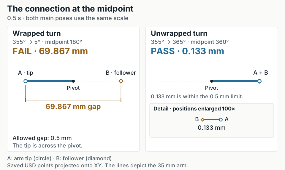
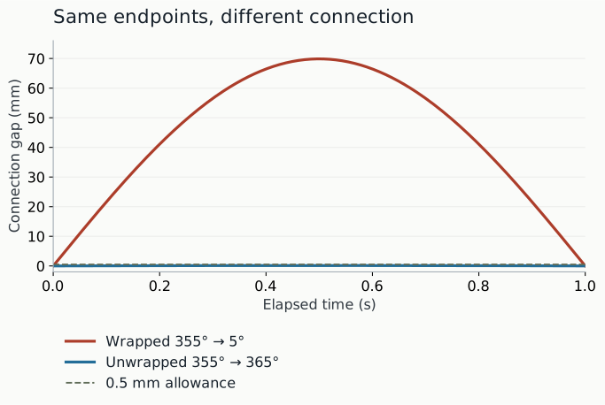
At the midpoint, the wrapped arm is at 180 degrees. Its pin is on the opposite side of the pivot from the follower. The measured gap is 69.867 mm. The unwrapped arm reaches 360 degrees and its measured gap is 0.133 mm, within the 0.5 mm allowance.
XY projections of points read from the saved USD controls at 0.5 seconds. The lines depict the 35 mm arm; these are diagrams of the measured positions. Both main views use the same scale. The unwrapped detail enlarges positions 100× so its small gap remains visible.
That small remaining gap is expected in this fixture: the follower interpolates along the chord between its endpoints while the arm tip follows an arc. Keeping it visible is more informative than constructing a passing control with zero error by definition.
I checked the midpoint numbers with a separate trigonometric expression. For radius r = 35 mm and an endpoint offset of 5 degrees, the gaps are r × (1 − cos(5°)) and r × (1 + cos(5°)). The expressions agree with the USD read-back to far below a micrometre in this run. This checks the calculation through a different expression; the same coding assistant implemented both, so it is not independent validation.
The origin-only baseline accepts both scenes. Checking only the connection at the endpoints also accepts both. Measuring the right relationship at the midpoint separates them.
Dense diagnostic samples of the saved USD controls. The threshold applies to the connection gap. A stationary arm origin would not reveal this separation.
A schedule can improve coverage and still miss motion
Uniform samples are simple to explain and reproduce. I compared that baseline with a schedule that also collects authored transform-key times affecting the two points, including their ancestors, and adds a midpoint between each adjacent time in that combined set.
The difference appears in a brief excursion authored around 0.12 seconds. Quarter-second samples see the connection before and after it has moved away. They pass. The key-aware schedule includes the excursion and measures a gap of 49.497 mm, so it rejects the scene.
That does not establish a generally better schedule. In another constructed scene, the arm makes two full turns between its start and end keys while the follower stays fixed at the starting pin position. The arm aligns with the follower at the endpoints and midpoint. A schedule containing only those three times passes. Quarter-second samples find the arm on the opposite side and measure a 70 mm gap.
Scroll sideways for more columns.
Constructed motion
Endpoints only
Quarter-second samples
Keys and interval midpoints
Short unwrapped turn
Pass
Pass
Pass
Wrapped scalar turn
Pass
Fail
Fail
Brief excursion around 0.12 s
Pass
Pass
Fail
Two full turns between keys
Pass
Fail
Pass
The table is why the pack reports its schedule and actual sample times. “Checked between keyframes” is too vague to support an acceptance decision. The two-turn control passes exactly what its three-time contract asks, while contradicting a stronger claim that the connection stays together throughout the interval.
A denser scan is useful for finding such examples, but density alone does not provide a continuous bound. A stronger guarantee would need assumptions about the allowed motion and a method that bounds the interval between measurements. This pack does not make that claim.
Apply it to the delivered assembly
The real application reuses the exact saved USD from the earlier assembly article, together with its delivered HDR dependency. No new production attempt was made. The test measures both ends of the connecting rod over the four-second animation, using eight uniform segments plus the relevant transform keys and midpoints.
That produces 481 sample times per connection. The largest measured crank-end gap is 0.003005 mm; the largest slider-end gap is 0.000955 mm. Both are below the existing 0.5 mm threshold.
For the failing control, I appended a 1 mm local translation to the rod pose in a separate copy. The resulting maximum gaps are about 1.003 mm and 1.001 mm, and the check rejects it. This offset is an injected defect. It was not present in the delivered artifact and should not be counted as an agent failure.
The first attempt to prepare this test bundle omitted the assembly’s HDR file. The harness returned insufficient evidence before reaching the connection checks. I retained that attempt and prepared a second bundle containing the original scene and its dependency. The accepted result therefore refers to the complete delivery, not a scene quietly stripped down until admission passed.
Other controls preserve the 35 mm arm’s result when stage distances are expressed in millimetres, exercise moving parent transforms, and request times beyond the authored duration. Missing clock metadata and uncovered intervals return insufficient evidence. The evaluator does not fill those gaps with a default timing assumption.
The next brief did not require constant speed
The September 24 evaluation supplied three more mechanisms under a different brief: a 42 mm crank radius, 140 mm rod, 25-degree starting phase and one counterclockwise turn in three seconds. All three passed the final selected artifact checks. The connection pack evaluated 769 times per connection; the largest recorded gap was about 0.009995 mm against a 0.5 mm allowance. Two separately declared diagnostic grids supplied another finite comparison at 514 times.
This evaluation also tested the interpretation of the brief. The analytical reference assumed constant speed, although the assignment left the speed profile open. My evaluating assistant corrected the mapping so that the uniform-speed comparison became advisory, while sampled phase, direction, loop closure and attachment remained required. A deliberately varied-speed copy then passed the required checks despite disagreeing with the advisory trajectory. Wrapped-angle and offset-rod copies failed the connection checks.
The brief’s wording introduced a different limit: attachment had to hold at any intended animation time. Every supplied mechanism passed the recorded samples, but all three broader assessments remained NEEDS_REVIEW because those samples do not establish the continuous claim. Neither a small measured gap nor a denser diagnostic grid removes that missing evidence.
Try a relationship contract
For the small arm control, the check parameters are:
Elapsed seconds are measured from the authored stage start. Local points use stage units; the gap threshold uses metres. The contract selects motion.connection, version 0.1.0, with check distance. Its full form is included beside every frozen scene.
The sampled connection-distance check is included in Scene Acceptance 0.5 on GitHub. It was not part of the earlier v0.3.0 release.
The v0.1 companion preserves the earlier code, eight constructed motion cases, original assembly bundles and reports, with private environment paths removed from the public copy. The later three-mechanism evaluation, supplemental checks and broader assessments remain in the private evaluation/fresh-producer-v1/ workspace, outside this companion. After installing the companion with the texture follow-up’s setup commands, run:
The matrix keeps origin, endpoint, uniform and dense diagnostic reports alongside the selected schedule. The assembly runner verifies its frozen bundles before and after evaluation. These are development tests built with coding-assistant help under my direction, using OpenUSD 25.11; the retained artifact adds a real application, but does not make the evaluation independent.
The companion and release 0.5 are separate snapshots. Use the companion commands above to reproduce the original sampling controls.
Keep a valid alternative beside the broken rod
The varying-speed control deserves a place beside the offset rod. One tests whether the evaluator allows a legitimate production choice; the other tests whether it rejects a broken connection. The supplied mechanisms alone did not expose our extra constant-speed assumption.
I would use the reported sample times to decide whether the check covers the animation’s use. For continuous attachment, the missed two-turn case still needs an answer. Requiring a uniform speed the owner never asked for would make acceptance stricter without solving that problem.
Disclaimer: The views and opinions expressed in this account are those of my own and do not represent those of my employer, NVIDIA.