Evaluating Physics Configuration and Simulated Behavior
A passing block still moved a millimetre; the trace and assumed friction explain what that pass means
Pradeep Kaushik·Sep 20, 2026·Build Note·10 min read·Updated Oct 3, 2026
In this article 9 sections
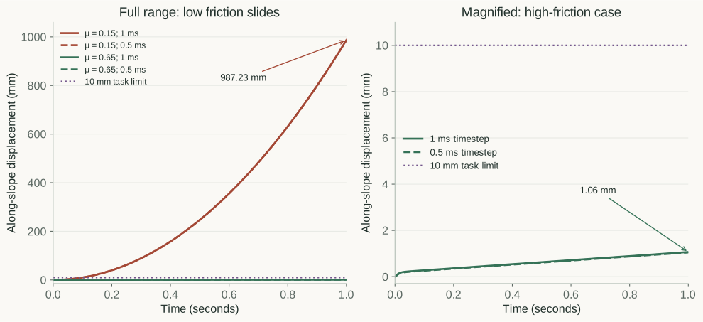
The higher-friction block passed the task, but it did not stay still. Its saved simulation trace showed about 1.1 mm of movement on a 20-degree incline. An ideal rigid-friction calculation predicted zero. The lower-friction block moved about 987 mm; both scenes passed the selected USD physics-configuration checks.
The task allowed up to 10 mm of movement over one simulated second, so the first result passed and the second failed. I kept the small displacement visible and reran both cases at half the timestep. The decisions survived that change, but neither run supplied evidence for the friction coefficients, which were assumptions.
After the animated assembly, I wanted to distinguish valid physics configuration from evidence that a simulated task succeeded. I kept this experiment to a block and ramp, where I could inspect the inputs and trace. The harness’s current simulation support is restricted to that model; the press-cell example later in this article needs a different evaluator.
You can reproduce the configuration checks through the acceptance harness and run the behavior experiment from its repository. The configuration adapter is an installed pack. In the public v0.3 replay below, the behavior runner remains a separate CPU experiment. Release 0.5 integrates this bounded worker as a selectable check.
The scene and the task contract
The coding assistant constructed the fixtures and runner under my direction. The protocol, inputs and expected decisions were frozen before execution. These are controlled tests of evaluation, not failures sampled from Astra or a model of a plant from my internal work.
Scroll sideways for more columns.
Input
Value used in the experiment
Block
0.2 × 0.2 × 0.1 m; authored mass 1 kg.
Fixed ramp
20-degree incline; block initially aligned with it.
Initial surface gap
0.1 mm.
Gravity
9.81 m/s².
Contact assumptions
Equal static and dynamic friction of 0.15 or 0.65; restitution zero.
Task
Maximum absolute displacement along the slope ≤ 0.010 m over one second.
Timestep comparison
1 ms and 0.5 ms with the other solver settings held fixed.
The two blocks start in the same pose. The replay uses body positions and orientations from the retained 1 ms simulation traces, with the same scale and ramp crop. One stays within the 10 mm limit; the other slides about 987 mm. Both pass configuration checks. The separate behavior experiment finds the task failure. Playback is slowed four times, with holds; friction remains assumed.
The GitHub project contains the protocol, runner and three USD fixtures. The third fixture has deliberately negative mass. It checks that the configuration stage can reject an invalid input before considering a useful behavior result.
The 10 mm limit is an illustrative requirement, chosen before observing the result. It is not a measurement of a physical assembly.
Configuration passed; the task separated the cases
The selected configuration checks accepted both positive-mass scenes. Applying the same displacement limit to their simulated motion separated them:
Scroll sideways for more columns.
Friction assumption
Selected configuration rules
Maximum displacement at 1 ms
Simulated task
0.15
Pass
987.23 mm
Fail: exceeds 10 mm.
0.65
Pass
1.06 mm
Pass: within 10 mm.
Negative-mass control
Fail
Not simulated
Configuration rejected.
Plotted from the recorded simulator traces, with separate scales for the full motion and the small displacement. Solid and dashed traces compare 1 ms and 0.5 ms timesteps. The 10 mm acceptance limit is an illustrative requirement, not a physical measurement.
For example, the higher-friction run’s summary contains these fields:
A short mechanics calculation gives a diagnostic comparison. An ideal rigid Coulomb model gives the lower-friction block downhill acceleration of approximately g × (sin(20°) − 0.15 × cos(20°)), or 1.97 m/s². Starting from rest, that predicts about 986.23 mm over one second. The larger coefficient exceeds tan(20°), approximately 0.364, so that idealized model can hold the block at rest.
The higher-friction simulation still moves about one millimetre, so the recorded result remains a small displacement rather than “stationary.” This experiment does not isolate the contributions of initial settling, numerical contact or integration. MuJoCo’s computation documentation describes the model behind those differences.
Halving the timestep produced approximately 986.73 mm and 1.05 mm. Both decisions stayed the same. The final-displacement differences were about 0.50 mm for low friction and 0.019 mm for high friction, with no simulator warnings recorded. That checks one numerical sensitivity. The coefficients are far apart, and these runs do not establish convergence, accuracy near the task threshold or correspondence with a real surface.
What each evaluation captures
The behavior experiment’s acceptance metric is the maximum absolute displacement along the slope over the run. The runner projects the change in position onto the downhill direction, then compares the largest magnitude with the declared limit. It does not decide from the final frame alone.
Scroll sideways for more columns.
Evaluation
What is actually checked or recorded
What it can reveal
USD configuration
The three selected upstream rules.
Invalid configuration, illustrated by negative mass.
Adapter readback
Supported structure and values used to write the simulator input.
A representation outside this bounded adapter’s support.
Simulated task
Along-slope displacement at every integration step against 10 mm.
A configured scene that fails the requested task.
Run diagnostics
Finite trace values and simulator warning counts.
An unusable trace or warnings needing investigation.
Timestep sensitivity
Final-displacement difference between 1 ms and 0.5 ms.
Dependence on that numerical setting in these runs.
Parameter evidence
Friction explicitly retained as assumed.
The missing basis for a claim about a real contact.
I kept the parameter question visible as an unresolved annotation. The prototype cannot acquire or authenticate a measurement, and the timestep comparison reports a difference without an independently chosen tolerance that would justify declaring convergence.
The same gap in a press-shop demo
On October 2, I asked for the harness to be run against the saved Astra demos. The older press transfer-cell report recorded PASS for all 24 selected general rules, including mesh rules with no applicable subjects. An earlier five-second PhysX run of that exact file had recorded 51.6 mm maximum wrist tracking error against a 10 mm requirement.
Scroll sideways for more columns.
Evidence for the same saved source
Result
What that result covers
Older general harness policy
24 rules returned PASS; empty mesh coverage was included in that count.
No issues reported under this policy. The scene uses 64 cubes; this is not evidence that polygon meshes were assessed.
Retained PhysX run, 2 ms timestep
Maximum tracking error 51.628 mm; limit 10 mm.
The simulated wrist failed the chosen tracking requirement.
Source identity comparison
SHA-256 matched.
Both reports refer to the same scene revision.
The comparison record and structural report preserve the older 24-rule policy separately from the newer 27-rule profile in the core article, which reports applicable subjects. The retained simulation report supplies the tracking result. The audit compared existing evidence; it did not rerun the simulation. The generic contract had no tracking target and did not read the trajectory, so the harness did not detect this behavior failure.
This is why I want the report to say what its pass covers. A tracking check needs the target motion, tolerance and a matching trace, plus an evaluator that understands that mechanism. The two-box MuJoCo adapter below cannot assess this articulated press cell. Its existing PhysX run also used placeholder masses and drive settings, so the tracking error is a result in that model, not a measurement of a real machine.
What the assembly would need for a physics task
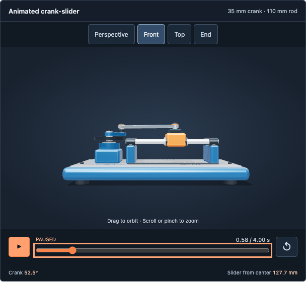
The ramp experiment starts with a declared physical model, even though its friction is assumed. Returning to the crank-slider, there is an earlier prerequisite: the delivery has no such dynamics model yet.
The front view helps inspect the assembly's structure. The animation prescribes its motion; this view is not a simulated response to gravity, friction or an applied load.
A separate read-only inspection of the submitted USD found no authored rigid-body, collision, mass or physics-material APIs, and no joints or physics scene. That is consistent with the original visualization brief. It is a missing prerequisite if I change the request to a rigid-body dynamics task.
For example, asking whether the slider can complete its stroke under a specified load needs more than replaying the existing animation. I would first define the load, drive and task limit, then require a suitable body/joint model, collision representation and consequential mass, inertia and contact parameters. Those are distinct concepts in USD’s physics schemas. Their values would need supplied evidence or explicitly approved assumptions.
The metal and rubber appearance does not provide those parameters. A four-second keyframed cycle also does not tell me whether an actuator can sustain it under load. No dynamics run or robot-training test has been performed on this assembly, and this project’s two-box adapter cannot ingest it. The block-on-ramp tests use a different representation. Extending the experiment to the assembly remains further work.
Libraries behind the experiment
The libraries supply scene access, configuration rules and numerical simulation. The project supplies the bounded conversion between representations, the task requirement and the interpretation of the recorded result.
Scroll sideways for more columns.
Library
What I reuse
Boundary in this project
OpenUSD 25.11
UsdGeom, UsdPhysics and UsdShade APIs to read geometry, units, mass and bound contact parameters.
The experiment’s reader admits only the supplied two-box scene structure.
NVIDIA USD Validation 1.20.0
MassChecker, RigidBodyChecker and ColliderChecker.
Installed configuration pack; these selected rules do not execute the task.
MuJoCo 3.6.0
CPU contact simulation and state integration.
Separate behavior runner using an explicitly generated MuJoCo model.
NumPy 2.5.3
Vector calculations and finite-value checks.
Compute displacement along the incline and inspect recorded numeric values.
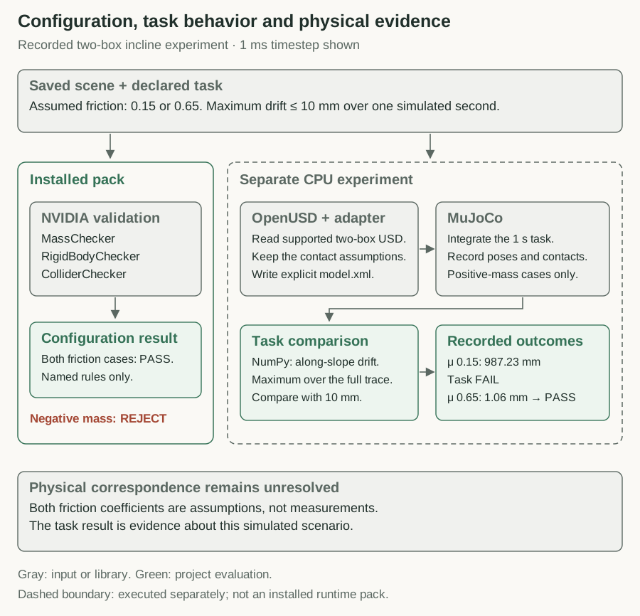
Historical v0.3 experiment, with the 1 ms results shown. Gray identifies inputs and libraries; green identifies project evaluation. The dashed boundary is the separate CPU runner, not an installed runtime pack. The displacement plot above provides the traces behind these outcomes.
Run the USD configuration checks
Start with the core installation steps. From the extracted project directory, add the pinned article dependencies and evaluate the low-friction fixture:
That returns ACCEPT_FOR_USE with exit code 0. Changing the fixture folder to negative_mass and choosing a new output directory returns REJECT with exit code 2. Each evaluation writes the common result.json and report.html.
The fixture’s full contract pins the nvidia.asset-validator pack to 1.0.0. Its one check selects these upstream rules:
This is an entry inside checks, not a complete contract. The adapter runs the named rules from NVIDIA USD Validation 1.20.0 and retains their issues, severity and locations. It does not invoke a fixer. With warnings_as_failures set to false, warnings remain in the report without failing this check.
Both positive-mass configurations produce no issues from those selected rules. The negative-mass control rejects, showing that these checks already go beyond syntax. Their scope is physics configuration: none of the three selected rules measures how far the block moves or verifies the source of its friction value.
Run the behavior experiment
The next command verifies the frozen input hashes, runs the configuration checks and executes four one-second CPU simulations: two positive-mass scenes at two timesteps. The negative-mass control is not simulated.
Use a new output path. The runner refuses to overwrite an existing run, and it checks the input hashes again after execution. It makes no model calls or robot-training runs.
A small adapter reads the frozen USD geometry, transforms, mass, gravity and bound physics material. It writes an explicit MuJoCo model for two boxes: a fixed ramp and a block with a free joint. This adapter admits only the supplied fixture structure; it is not a general USD importer.
The contact pair has explicit friction values, avoiding dependence on implicit material-combination rules. MuJoCo 3.6.0 integrates the pose. The runner then records position, orientation and contact count at every step. The emitted model.xml retains the solver and contact settings so those are available for inspection. MuJoCo’s contact documentation explains how pair parameters affect that model.
For a developer inspecting one run, these files answer different questions:
Scroll sideways for more columns.
Output below /tmp/incline-physics-01
What to inspect
summary.json
All decisions, versions, hashes and timestep comparisons.
low_friction/configuration/result.json
The selected NVIDIA rule results.
low_friction/adapter-readback.json
Parameters actually read from the USD fixture.
low_friction/dt-0.001/model.xml
Model and solver settings passed to MuJoCo.
low_friction/dt-0.001/trace.csv
Recorded poses, contact counts and along-slope displacement.
low_friction/dt-0.001/summary.json
Maximum displacement, task decision and warning count.
The other positive-mass case and timestep use the same layout. The configuration reports use the harness’s report format; the behavior summaries use this experiment’s own format.
Use the results without changing the problem
The high-friction simulation met the 10 mm limit under its saved model and solver settings. Both coefficients remain assumptions, so deciding whether an actual part will stay on an actual incline still requires evidence about that contact.
To adapt the project, keep the supplied experiment intact and create a separate protocol and fixture set. The runner checks frozen hashes; replacing its input scene is deliberately not the extension mechanism. A new test needs a supported conversion, an independently chosen task limit, valid and invalid controls, and a record of which parameters were supplied, assumed or measured. For the crank-slider, that starts with the load and acceptable response before a dynamics conversion.
Release 0.5 carries this restricted CPU worker’s result into the common report. The worker follow-up explains the evidence handoff and why a 664 mm slide was acceptable under a different production brief. The commands above preserve the publicly reproducible standalone experiment. Neither path acquires measured friction or makes this adapter suitable for an arbitrary USD mechanism.
I would not let a producer turn the failed 987 mm result into an accepted model of an existing contact by increasing friction until it passes. That coefficient describes the contact being modeled and needs evidence or an owner-approved assumption. Exploring a different surface is a legitimate new scenario, but it changes the question. For the original question, the failed result stays in the record until there is a supported reason to change the model.
Disclaimer: The views and opinions expressed in this account are those of my own and do not represent those of my employer, NVIDIA.