The imitation-learning run I built began with ten Franka demonstrations I downloaded. They were enough to test everything downstream, but they arrived as finished files. I could not see what had been measured directly, what had been estimated or what had already been lost before the demonstrations reached me.
I had given Capture one paragraph in the robot training loop. To choose the hardware, I needed to go back to what each demonstration had to contain: what the robot observed, the action it should learn, and whether those measurements stayed aligned in time.
The product examples below are current to August 2026.
A refinery valve operation sets the requirements
In my work in refineries, I saw how ordinary maintenance tasks become difficult because of where they have to be done. Operating a valve, replacing a part or tightening flange bolts can place a technician among dense pipework or in an area where human exposure needs to be limited.
I will use valve operation through the article. The robot enters the process area, locates a manual valve, engages the handwheel, turns it by the requested amount and stops before reaching its mechanical limit. The plant model gives its approximate location; the exact handle orientation depends on where the last operator left it. The capture record must preserve how the robot finds the valve, makes contact, applies load, turns and knows when to stop.
When people picture a general-purpose humanoid at home, they usually picture chores such as folding clothes, loading a dishwasher or tidying a room. The industrial counterpart I find more interesting is a robot that extends the reach of a maintenance technician across this kind of work. This is one frontier for industrial robotics because maintenance combines varied equipment, irregular spaces, tool use and contact, and the work rarely unfolds exactly the same way twice.
That variety changes the capture strategy. Operating a valve needs wrist pose and force. Handling a cable needs finger motion and tactile contact. A mobile manipulator adds base motion and changing camera views; a bipedal humanoid adds torso motion, foot contact and balance. For the valve task, I would not choose glove data as the primary signal. The robot body and task decide what Capture has to preserve.
The task does not automatically need a learned policy. With one valve in a fixed location, conventional programming and force control are simpler. Demonstrations become useful when access, pipework, handle orientation or tool alignment vary enough that the robot must adapt. The controller still enforces the valve’s mechanical and torque limits.
Motion is only part of the episode
For direct imitation learning, Capture produces a demonstration recorded over time. Each step contains an observation, the action sent to the robot and the following response. Typical observations include camera frames, joint state and contact signals; actions include joint movements, end-effector targets or gripper positions.
If the robot was told to turn the valve but its tool slipped from the handwheel, a command log alone would hide the failure. I want the command kept beside the next image, joint state and force reading so I can distinguish what the robot was asked to do from what happened.
A degree of freedom, or DoF, is one independent number needed to describe motion. A wrist moving freely through space has six: three for position (x, y, z) and three for orientation, often represented as roll, pitch and yaw. Together they form its pose: where it is and which way it points relative to a coordinate frame.
Hand shape is a different measurement. A human hand has more than 20 DoF because the fingers bend at multiple joints. A glove records finger articulation and, depending on the design, wrist orientation. It usually does not provide absolute six-DoF wrist pose in the robot frame. MANUS, for example, pairs hand data with a separate tracking system for absolute position and rotation. The glove and tracker solve different measurements.
Force and tactile sensing are related, but different. A wrist force-torque sensor reports the load at the tool. Tactile sensors show pressure across the fingers and help detect local contact or slip. An egg, a slippery bottle and a charging cable require different finger pressure even when the wrist follows a similar path.
Flange maintenance makes the requirement explicit in another way. A robot removing and reinstalling bolts around a pipe or heat-exchanger flange must identify each bolt, follow the tightening sequence, reach the specified torque and control contact with the tool. A representative robotized pipe-flange study combined torque control with active compliance and still found that one camera did not show enough of the operation. A glove and wrist tracker cannot recover those contact signals by themselves.
Visibility decides which tracker survives
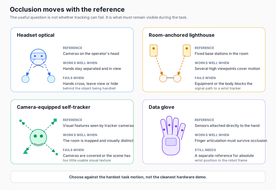
I used to ask whether a tracker could handle occlusion without specifying what was being blocked. A wrist hidden behind equipment may disappear from a room-mounted system, while a self-tracking device can keep working if its own cameras still see enough of the room. Headset cameras have another problem when hands cross or hide each other. A glove can preserve finger articulation in those moments, but I still need a separate way to locate the wrist.
Scroll sideways for more columns.
Device or tracking source
What it captures well
What I would test first
Headset optical hand tracking
Finger shape and wrist pose with little extra hardware
Crossed hands, poor lighting and hands hidden by the object
Data glove
Finger articulation when cameras cannot see the joints
Fit, calibration and the separate source for wrist position
Inside-out headset-tracked controller
Six-DoF wrist pose without instrumenting the room
Loss of tracking and error in the wrist-to-controller offset
Lighthouse tracker
Room-anchored six-DoF pose from multiple viewpoints
The body or equipment blocking the base-station signal
Camera-equipped self-tracker
Six-DoF pose without base stations or headset line of sight
Covered cameras, plain surfaces and robot-frame alignment
Optical motion capture
Marker-based wrist or full-body pose
Hidden markers, room calibration, setup time and cost
Two HTC products show the spectrum. The VIVE Tracker 3.0 uses SteamVR base stations; the VIVE Ultimate Tracker uses cameras on the tracker. Both report six-DoF pose, but what must remain visible differs. PICO’s Motion Tracker is another object-tracking option.
I am not recommending any of these products or presenting a complete market comparison. Other vendors cover similar ground. Current compatibility, SDK access, mounting and performance during the actual task still need to be checked before buying.
For the valve task, the first test is the full motion in a representative mock-up: approach through the pipework, find the handwheel, engage it, turn and retract. Occlusion comes first because the task exposes it quickly, but it is not the only test. A rig that survives the motion still has to meet the required accuracy, repeatability, latency and control rate. The rest of the check covers jitter, calibration drift, operator comfort and whether the system exposes raw measurements or only a processed pose.
Every choice puts the reference somewhere different. The task decides which line of sight is most likely to survive.
Captured motion still has to become a robot command
Pose describes where something is. The action representation describes what the controller is asked to do next. The same captured wrist motion can be represented as an absolute end-effector target, a small change from the current pose, joint-position targets or joint velocities. That choice must match the robot controller and the policy that will learn from the data.
For a contact-rich task, position is not the whole action. The policy can also produce a desired force, torque or six-axis wrench, which combines three forces and three torques, or ask the controller to change stiffness as contact begins. Those commands are different from the force-torque sensor reading. One records what the controller was asked to apply; the other records what the robot experienced.
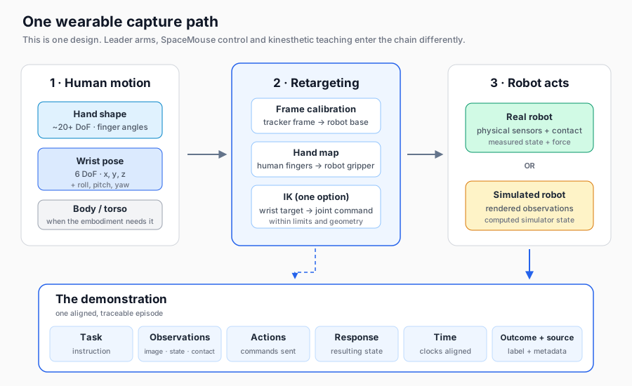
Retargeting converts human measurements into that robot representation. Calibration relates the tracker, camera and robot coordinate frames. Inverse kinematics can turn an end-effector target into joint commands, but that is one route rather than the definition of retargeting. A bad transform can produce smooth motion in the wrong place.
A wearable rig is also only one way into Capture. A leader arm measures another arm’s joints directly. Kinesthetic teaching records the robot while a person physically guides it. A 2025 study compared kinesthetic teaching, VR and SpaceMouse teleoperation in three tabletop tasks. Kinesthetic teaching produced the cleanest data and best downstream performance, but participants did not prefer it for large-scale collection because of the physical load. The Universal Manipulation Interface uses handheld grippers and wrist-view cameras to collect robot-compatible demonstrations away from the robot.
One wearable path. The inverse-kinematics route shown here is an example; other interfaces enter the chain differently.
The episode needs its own evidence
Choosing a rig solves the measurement problem. Capture also has to produce an episode I can trust. That depends on knowing where every value came from, whether the streams stayed aligned, and what failed during collection.
The July 2026 preprint Data Pyramid for Embodied Manipulation is a good broader read on real-robot, UMI-style, human video, simulation and general vision-language data. The public GR00T N1 data discussion shows a simpler pyramid. Neither implies one fixed recipe; the proportions depend on the task.
Ground truth is not one layer of that pyramid. Each source can be ground truth for one variable while estimating or omitting another. A simulator knows the object pose defined inside its world, but its contact model may not match reality. A real robot can measure joint positions and forces, but may estimate object pose from cameras. Human video records real images over time, but usually has no robot action attached. The episode should record whether every stream was provided by a simulator, measured by a sensor, estimated by software or missing.
Calibration and synchronization are the first silent failures to check. Suppose the hand moves at 0.5 metres per second. A 50-millisecond clock offset pairs the action with an observation about 2.5 centimetres away from where it belongs. At a 20 Hz control rate, that is one full step. Near contact, it can pair the turn command with an image taken before the tool touched the valve.
Failure data is not bad data. It becomes ambiguous in behavior cloning, the direct imitation of demonstrated actions, when the policy does not know which attempts succeeded. With the right labels, failed transitions can help train a recovery policy or a success model. I would keep the failed attempt, correction and successful recovery as a labeled sequence rather than mix unexplained failures into the success set.
Before accepting an episode, I would check its outcome, observations, actions, response, units, coordinate frames, timing, calibration and source. Then I would look across the valve collection: did it cover different approach angles, heights, handle orientations, pipework occlusion, requested turns, torque ranges and slip recoveries? A set of well-recorded demonstrations can still leave out the situations the robot will face.
For the valve task, I would start by walking through the full motion and marking where I need pose, contact, robot state and timing. Then I can test a capture setup against those requirements, including the moments when the tool slips or disappears behind pipework.
Disclaimer: The views and opinions expressed in this account are those of my own and do not represent those of my employer, NVIDIA.